555 Timer Circuit Schematic / This means that the output voltage is a periodic pulse that alternates between the vcc value and 0 volts.. The standard 555 timer ic is used in a variety of timer, pulse generation and oscillator applications. The good thing is that this chip could work directly with 12v so no driver for the mosfet is needed. This cycles 60 times every second. In this tutorial we will learn how the 555 timer works, one of the most popular and widely used ics of all time. This tutorial provides sample circuits to set up a 555 timer in monostable, astable, and bistable modes as well as an in depth discussion of wiring info:
Basically, this means that you will have a continuous transition from a high voltage level (determined by and slightly less than your supply voltage) to 0v at a certain frequency (number of times per second). A better circuit is using a 555 timer. This is the schematic below for the 555 timer that creates one square wave output. Clap switch circuit using ic 555 timer & without timer. The 555 timer is a simple integrated circuit that can be used to make many different electronic circuits.
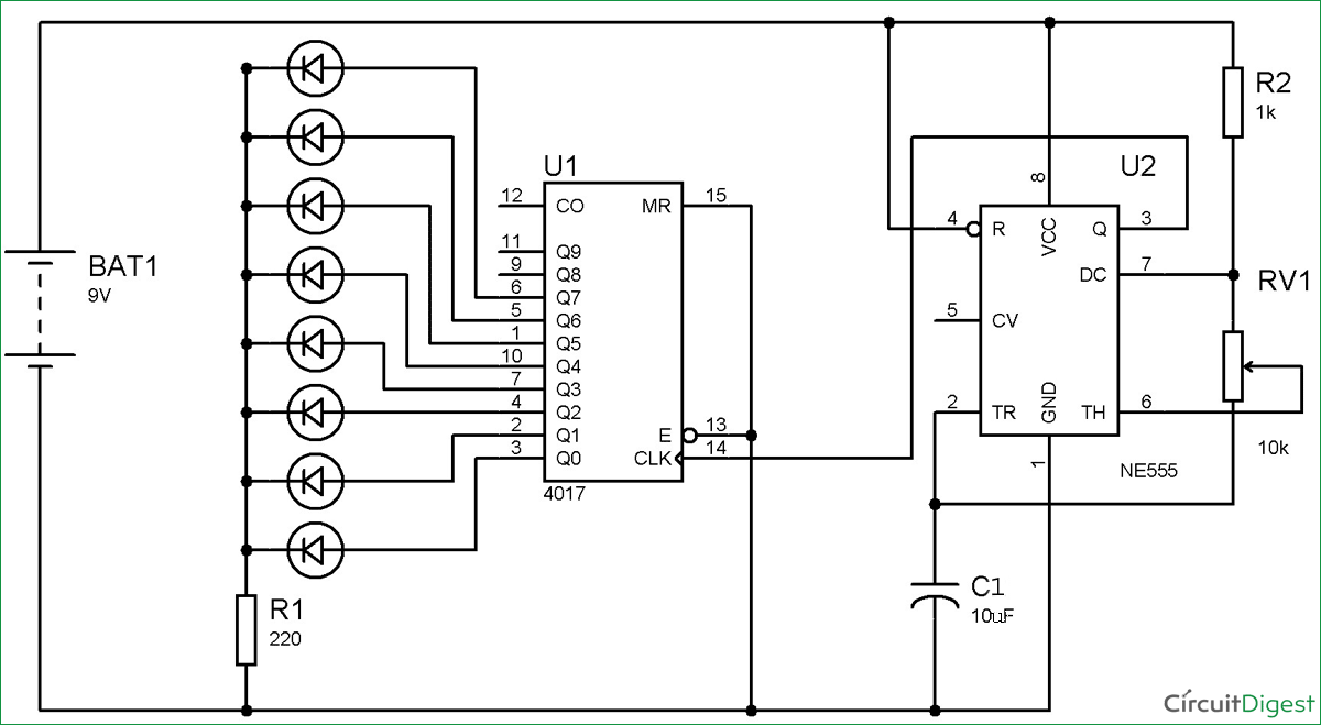
LED Roulette Circuit using 555 timer IC - ArRoboticsBlog from circuitdigest.com The timer generates an output pulse with an on time period determined by the rc network i.e t = 1.1rc. The lm555 has a maximum typical supply voltage rating of 16v while the relay's armature coil is enabled at 12v. A better circuit is using a 555 timer. It is a affordable, stable and user friendly ic in application such as monostable and bi stable. The breadboard schematic of the above circuit is shown below. 7 below, you'll see the circuit schematic of the 555 and the parts relevant to it. In this circuit, we will build a clock of about 60hz. The 555 timer is an integrated circuit, it is extremely versatile and can be used to build lots of different circuits.
Basically, this means that you will have a continuous transition from a high voltage level (determined by and slightly less than your supply voltage) to 0v at a certain frequency (number of times per second).
The 555 timer is configured as a monostable multivibrator. Learn about the 555 timer and how it works in astable mode. Finally, power up your circuit by connecting the battery to your breadboard Therefore, at low astable frequencies lm555 complimentary outputs schematic timer b in this method acts as a voltage comparator and has no timing function. Astable mode can produce digital square waveforms that go back and forth between. Generally, it's miles a monolithic timing generally, it's miles a monolithic timing circuit that offers unique and surprisingly stable delays of time or oscillation. Look at the circuit diagram. The 555 timer ic is an integrated circuit (chip) used in a variety of timer, delay, pulse generation, and oscillator applications. So far i have tried drawing from this link which was supposed to produce. A 555 timer is a very versatile. The output of uc (upper comparator) which is reset input to rs latch is high when the threshold input is high or. One configuration of this timer creates a perfect square wave. The 555 timer is an integrated circuit, it is extremely versatile and can be used to build lots of different circuits.
Taking apart a circuit board or module and reconstructing its complete schematic is a valuable skill. The circuits explained here are 10 best small timer circuits using the versatile chip ic 555, which generates predetermined time intervals in response the image shown below represents the internal schematic of a standard ic 555. The 555 timer can provide time delays ranging from several minutes for one cycle of operation to many. The 555 and 7555 are called timers or timer chips. The 555 timer is a simple integrated circuit that can be used to make many different electronic circuits.
555 Timer Astable Multivibrator Circuit - Technology & Hacking from circuitdigest.com Over 100 of 555 timer circuits and projects including the ic datasheet. The output load is driven by the relay switch which is in turn controlled by the timer circuit. The schematic is shown in fig 5. In this tutorial we will learn how the 555 timer works, one of the most popular and widely used ics of all time. This cycles 60 times every second. Clap switch circuit using ic 555 timer & without timer. It is a slave to timer. 555 timer was first introduced by signetics corporation in 1971 as se555/ne555.
The 555 timer shown above is configured as an astable circuit.
The breadboard schematic of the above circuit is shown below. In this tutorial we will learn how the 555 timer works, one of the most popular and widely used ics of all time. It's a simple source of oscillating in the schematic above, notice that the threshold pin and the trigger pin are connected to c1. In this circuit, we will build a clock of about 60hz. I used a 9v supply. Finally, power up your circuit by connecting the battery to your breadboard But when i complied, i got this. Clap switch circuit using ic 555 timer & without timer. Therefore, at low astable frequencies lm555 complimentary outputs schematic timer b in this method acts as a voltage comparator and has no timing function. A 555 timer is a very versatile. This 555 timer is in astable mode. The 555 timer shown above is configured as an astable circuit. Learn about the 555 timer and how it works in astable mode.
Over 100 of 555 timer circuits and projects including the ic datasheet. To make the same circuit as mentioned above without ic 555 timer, we will have to use the following basic electronic components and devices. These styles of ics are very. It is a slave to timer. The breadboard schematic of the above circuit is shown below.
555 Timer Tutorial - The Monostable Multivibrator from www.electronics-tutorials.ws And now a full schematic of the 555 timer oscillator with single step and free run option. It is a affordable, stable and user friendly ic in application such as monostable and bi stable. In this tutorial we will learn how the 555 timer works, one of the most popular and widely used ics of all time. Frequency is 1000 hz then c2 will have greater benefit than if the oscillator frequency is 10 hz. The standard 555 timer ic is used in a variety of timer, pulse generation and oscillator applications. So far i have tried drawing from this link which was supposed to produce. Here is a code that can be used as a framework for your circuits, here is how to create new components and use them as if they were components in cad. We can see that it us made up of 21 transistors, 4 diodes, and 15.
You can either follow the previous schematic or follow the breadboard wiring diagram below.
One configuration of this timer creates a perfect square wave. Si notation all the schematics in this ebook have. To observe the 555 timer in astable mode, let's build a circuit that uses the 555 timer's oscillating output to make. A 555 timer is a very versatile. These styles of ics are very. We can see that it us made up of 21 transistors, 4 diodes, and 15. The 555 timer is a simple integrated circuit that can be used to make many different electronic circuits. The schematic is shown in fig 5. Frequency is 1000 hz then c2 will have greater benefit than if the oscillator frequency is 10 hz. The 555 timer ic is an integrated circuit (chip) used in a variety of timer, delay, pulse generation, and oscillator applications. This is the schematic below for the 555 timer that creates one square wave output. To make the same circuit as mentioned above without ic 555 timer, we will have to use the following basic electronic components and devices. I used a 9v supply.
The good thing is that this chip could work directly with 12v so no driver for the mosfet is needed 555 timer schematic. This tutorial provides sample circuits to set up a 555 timer in monostable, astable, and bistable modes as well as an in depth discussion of wiring info:


0 Komentar